The tunnel waterproofing sheet laying construction template is a temporary structure used to support and fix the waterproofing sheet, ensuring that the waterproofing sheet remains flat, firm and achieves a strict waterproofing effect during the laying process of the tunnel inner wall. This template needs to be specially designed according to the geometric shape of the tunnel (such as arch, circle or horseshoe) to meet different construction needs. It is usually made of materials such as steel frame, aluminum alloy, wood board or fiberglass, and is adjustable and reusable. The application of the template can effectively prevent the waterproofing sheet from wrinkling or damage due to uneven force, and ensure the tight connection of the joints, providing long-term waterproof protection for the tunnel.

Tunnel Waterproof Board Laying Formwork

Tunnel Waterproof Board Laying Formwork

Tunnel Waterproof Board Laying Formwork

Tunnel Waterproof Board Laying Formwork

Tunnel Waterproof Board Laying Formwork

Tunnel Waterproof Board Laying Formwork

Tunnel Waterproof Board Laying Formwork

Tunnel Waterproof Board Laying Formwork

Tunnel Waterproof Board Laying Formwork

Tunnel Waterproof Board Laying Formwork

Tunnel Waterproof Board Laying Formwork

Tunnel Waterproof Board Laying Formwork

Tunnel Waterproof Board Laying Formwork

Tunnel Waterproof Board Laying Formwork

Tunnel Waterproof Board Laying Formwork

Tunnel Waterproof Board Laying Formwork

Tunnel Waterproof Board Laying Formwork

Tunnel Waterproof Board Laying Formwork
|
Trolley length |
L = 3400 mm (car track spacing) |
|
Trolley walking speed |
6m/min |
|
Level adjustment amount |
none |
|
Hydraulic system working pressure |
P=12MPa |
|
Track center distance |
8000mm 卤 5mm |
|
Maximum stroke of the cylinder |
vertical cylinder 300mm |
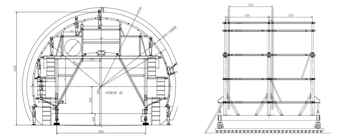
Tunnel waterproof board laying formwork is a non-standard product specially designed and manufactured for the lining of various tunnels and culverts. The whole roll of tarpaulin is hung on the trolley; the bottom end of the tarpaulin is fixed, the tarpaulin can be automatically unfolded, and the tarpaulin can be stopped at any position of the track at any time; and the reverse function is also provided. It can greatly save the labor cost of hanging tarpaulin.
The working process of the tunnel waterproof board laying formwork is carried out in the following steps:
CHECK WHETHER THE TUNNEL CONSTRUCTION CONDITIONS MEET THE DESIGN REQUIREMENTS OF THE TUNNEL WATERPROOF BOARD LAYING FORMWORK:
Since the tunnel waterproof board laying formwork is a non-standard equipment, the conditions of use must meet the design requirements before use.
Check whether the road surface elevation and road surface condition meet the design requirements, the road surface elevation: as shown in the figure; the road surface condition: concrete road surface.
Check that all the bolts of the trolley are tight, and check whether the trolley, pulley, winch, etc. are firmly installed.
Check whether the sleepers and rails meet the design requirements;
Check if the circuit meets the design requirements;
Check if the tarpaulin is hung (it will not fall off and can rotate freely).
Hanging tarpaulin:
The tunnel waterproof board laying formwork walks to the position where the tarpaulin needs to be hung. Hang the tarpaulin in the following steps:
Lift the entire roll of tarpaulin onto the work platform and drive the car to the working platform.
Remove the shaft between the carts and put the tarpaulin on the shaft.
Operate the winch to adjust the trolley to the position of the shaft.
Connect the shaft to the trolley firmly. Tarpaulin installation completed
Install tarpaulin:
Operate the winch to walk the trolley to the bottom end of the track;
Unfold the tarpaulin, connect and fix the end of the tarpaulin with the tarpaulin reserved by the inverting arch;
Operate the hoist to move the trolley up to the top of the next position that needs to be fixed, and go back some, fix the tarpaulin, and push it in.
Hang up a tarpaulin on the work platform after the tarpaulin is used up.
Walking:
After hanging a lap of tarpaulin, first close the gantry support jack and start the walking motor to walk. Tunnel waterproof board laying formwork should pay attention to the following points when walking:
The tarpaulin of the trolley cannot be connected to the tarpaulin already installed.
Tunnel waterproof board laying formwork must be completely static before you can change direction.
When the slope of the rail is too large, and the trolley is slipping, you can sprinkle some dry sand onto the rail surface to increase the adhesion and make the slip phenomenon disappear.
Repeatedly circling the tarpaulin, installing the tarpaulin, and walking, the entire operation of the Tunnel waterproof board laying formwork was completed.
Precautions:
Before each work cycle, check whether the rail is straight and check the tightness of the rail. Before the trolley is in place, it is necessary to straighten the rails and strictly prevent the phenomenon that the gantry support jacks cannot be supported on the rails.
After each work cycle, check the tightness of the bolts and pins of each part, and re-inspect and tighten the various joints.
The trolley walking mechanism and the jack should be regularly buttered.
The hydraulic system should be free of leakage. The hydraulic oil should be clean. The pressure gauge switch should be opened during operation to observe the fluctuation of pressure at any time.
When the tunnel waterproof board laying formwork is walking, pay attention to obstacles such as air ducts and water pipes on the ground to prevent the towing phenomenon when the trolley is walking.
For the safety of you and others, please operate the trolley according to the specifications and be diligent in maintenance to prevent all accidents.
It is necessary to introduce a three-phase four-wire power supply, otherwise the leakage circuit breaker will not function as a leakage protection trip.
The green indicator on the panel of the power distribution box is the power indicator.
Oil pump motor thermal relay setting current: 11.6A.
Hydraulic system component table
|
NO. |
Name |
Specification type |
Unit |
Quantity |
Remarks |
|
1 |
Lifting cylinder |
YGJDK-160/90F |
article |
4 |
|
|
2 |
Translation cylinder |
HSGK-100/55E8501 |
article |
0 |
|
|
3 |
Multiple way reversing valve |
DLF-B15F-T/3C8P |
Piece |
1 |
|
|
4 |
Oil pump |
PFE-XP-F320CFP |
Piece |
1 |
|
|
5 |
Throttle valve |
LA-H10L |
Piece |
4 |
|
|
6 |
Oil level gauge |
YWZ |
Piece |
1 |
|
|
7 |
Oil filter |
ZV-A40 |
Piece |
1 |
|
|
8 |
air filter |
QVQ3 |
Piece |
1 |
|
|
9 |
Motor |
Y132S-4B3 |
Piece |
1 |
5.5kw |
|
10 |
Pressure gauge |
Y60 |
Piece |
1 |
0—25Mpa |
|
11 |
Pressure gauge switch |
KF-L8 |
Piece |
1 |
|
|
NO. |
Name |
Specification model |
Unit |
Quantity |
Remarks |
|
1 |
Leakage circuit breakers |
NM10-100/330-100A |
One |
1 |
|
|
2 |
Fuse |
RT14 |
One |
2 |
|
|
3 |
Fuse core |
RT14-20 |
One |
2 |
|
|
4 |
Contactor |
JT1-40A/38W |
One |
2 |
|
|
5 |
Motor |
Y132M2-6 |
station |
4 |
1.1KW |
|
6 |
thermal relay |
JR36-63 45A |
One |
1 |
|
|
7 |
Indicator light |
AD11 |
One |
3 |
|
|
8 |
Button |
LA19-11 |
One |
4 |
|
|
9 |
Distribution box |
500x400x200 |
station |
1 |
|
|
Job project |
Technical requirements and instructions |
|
Walking system |
Drive chain and grease |
|
Various bolts |
There should be no looseness or slippery phenomenon |
|
Various jacks, cylinders |
Should be in the working size position when working |
|
Walking mechanism (when walking) |
Smooth transmission, no abnormalities |
|
Check the joystick (no load) |
It should be easy to operate, accurate in position and reliable in positioning |
|
Electrical control system |
According to the electrical instructions |
|
Hydraulic system |
|
|
Check the amount of oil in the hydraulic tank |
The amount of oil is sufficient |
|
Check each tubing connector |
No leakage, no aging |
|
Check oil temperature |
The oil temperature is maintained at 30-70 during operation. C |
Routine maintenance of the car (secondary maintenance for 15 cycles per work)
|
Job project |
Technical requirements and instructions |
|
Complete a maintenance project other than the maintenance work at this level |
|
|
Jacks, work platforms |
The jack rotates flexibly, the hinges must not be deformed, and the working platform should be stable and firm. |
|
Machine |
|
|
Check each bolt |
Should be fastened without slipping |
|
Weld of the gantry and upper arch |
No cracking, otherwise it should be repaired |
|
Overall size inspection |
Height, width and clearance should be within the tolerance of the drawing design size |
|
Next cycle rail laying inspection |
Before each cycle, check whether the rail is horizontal, parallel and accurate, and whether the gauge is accurate. Whether the tunnel lining center and the gauge center are within the error tolerance. |
|
Electrical control section |
The working voltage is 380V, the voltage is stable, and no leakage is allowed. |
|
Hydraulic system |
|
|
Check the hydraulic system control components |
Is it in a controllable state |
|
Check each pipe and pipe joint |
No leakage |
|
Check system tightness |
Eliminate leakage |
|
Cleaning filter |
Clean |
|
Detect oil temperature |
The oil temperature is at work 30-70。C |
Inventory all parts and match the packing list.
Check if the fuel tank is clean, cover the fuel tank cap, and add 115 liters of clean YA-N46 hydraulic oil from the tank air filter.
according to the requirements of the cylinder layout
Before welding the pipe, the burr of the pipe head should be removed, (with a round file), and the high-pressure wind blows the debris inside the pipe.
The welded pipe should be aligned, welded, and not allowed to leak oil.
Pipe the pipe according to the requirements of the pipe, install all the gaskets, rings, and clean the debris in the pipe.
Connect the multi-way reversing valve and cylinder to the pipeline (the mechanical lock cylinder must be connected to the left and right valves of the multi-way reversing valve).
Note: There are no 1, 2 hoses.
Jog the motor to check the motor steering and start the oil pump to test each cylinder (the pressure has been adjusted at the factory). If the system pressure is not established (the cylinder does not move), first check whether the joints of the pipes are leaking oil, and if necessary, exclude them. Then adjust the relief valve to see the pressure from the pressure gauge is 12MP. After adjusting, close the pressure gauge switch and pay attention to the oil level.
Clean the oil filter element frequently and remove the filter debris. Replace it when it is blocked.
After the first refueling, replace the new oil in three cycles, and then change the hydraulic oil condition irregularly. It is recommended to replace the new oil in 30 cycles.
|
Fault phenomenon |
Reason |
Approach |
|
The motor does not start properly |
1. The circuit fuse is broken |
1, replace the fuse |
|
2. The thermal relay normally closed contact JR is not reset |
2, reset the contact to close it |
|
|
3. Normally closed contact bad contact |
3, repair contacts |
|
|
4. Poor contact or break between the start and stop buttons |
4, connect the line, repair button point |
|
|
One of the positive and negative buttons can control the motor and the other cannot control the motor. |
1. There is a button contact in the anti-control button. |
1, repair contacts |
|
2. There is an interlocking normally closed contact in the positive and negative control buttons. |
2, repair the contacts, make it closed |
|
|
No positive or negative buttons can be activated |
1. The reverse contactor coil is damaged. |
1,replace the contactor coil |
|
2. The thermal relay normally closed contact is not reset. |
2, reset pad relay normally closed contact |
|
|
3. Check if the power supply and plug are loose. |
3,inspection, replacement |
|
|
4. Check if the stop button is damaged or if its line is connected. |
4,inspection, replacement |
Gaofei
Address: 200m east of tulip garden, group 12 of zhangling community, hongshan street office, hongshan town, xigong district, Luoyang
Tel: +8616638856888
Contact: Gaofei Huang
Mobile: +86-18637923976
Phone: 0379-80881719/ 0379-60162687
QQ: 286827457
E-mail: gaofei@gf-bridge-tunnel.com


