A convenient structural design. This channel is usually located on the side wall or bottom of the tunnel. Its main function is to ensure that water, mud or other media can pass smoothly during construction without affecting the construction of the main formwork system and concrete pouring.

Tunnel Formwork Bypass Channel

Tunnel Formwork Bypass Channel

Tunnel Formwork Bypass Channel

Tunnel Formwork Bypass Channel

Tunnel Formwork Bypass Channel

Tunnel Formwork Bypass Channel

Tunnel Formwork Bypass Channel

Tunnel Formwork Bypass Channel

Tunnel Formwork Bypass Channel

Tunnel Formwork Bypass Channel

Tunnel Formwork Bypass Channel

Tunnel Formwork Bypass Channel
|
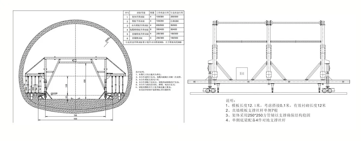
Length of each lining of the trolley |
L=12100 mm |
|
Clearance size |
B H = 6500 mm 脳 4500mm |
|
Trolley walking speed |
6m / min |
|
The amount of horizontal adjustment |
100mm (single side) |
|
System working pressure |
P = 12MPa |
|
Rail center distance |
7600mm 卤 5mm |
|
The maximum stroke of the cylinder |
Vertical cylinder: 300mm |
The tunnel formwork channel is a non-standard product specially designed and manufactured for the concrete lining of water tunnels such as tunnels and culverts. It has the functions of vertical mold and demoulding function, high surface finish of lining and fast lining speed. The working process of the steel formwork trolley is carried out in the following steps:
FIRST, CHECK WHETHER THE TUNNEL CONSTRUCTION CONDITIONS MEET THE DESIGN REQUIREMENTS OF THE TEMPLATE TROLLEY:
Since the formwork trolley is a non-standard equipment, the conditions of use must meet the design requirements before lining.
Check whether the road surface elevation and road surface condition meet the design requirements, the road surface elevation: as shown in the figure; the road surface condition: concrete road surface.
Check whether the sleepers and rails meet the design requirements;
Check whether the outer surface of the steel formwork is coated with a release agent.
SECOND, THE VERTICAL MODEL
After the tunnel formwork channel walks to the lining position, the vertical form can be established, and the tunnel formwork channel is in the demolished state before the vertical mold. The vertical mold is carried out in the following steps:
After the trolley is in the lining position, the gantry support jack is supported on the rail and tightened.
Start the hydraulic motor and operate the manual reversing valve handle to lower the vertical cylinder and the secondary cylinder. Adjust the Tunnel formwork channel template to a predetermined height;
Operate the manual reversing valve handle to translate the horizontal cylinder. Adjust the Tunnel formwork channel template so that its centerline is aligned with the lining centerline, and then operate the manual directional valve to bring the straight wall template to the desired position and tighten the lateral jack.installed the ground screw jack, plug board.
THIRD, GROUTING
Grouting can be performed after the vertical mold is completed. Before the grouting, the outer surface of the tunnel formwork channel should be coated with a release agent to reduce the surface tack during demolding. When grouting, take care to ensure that the height of the concrete in the middle of each tank is basically the same, preventing the template from running.
Pay attention during the grouting work: Before each grouting, check whether the lead screw and the jack are loose to prevent the trolley from deforming during grouting.
FOURTH, DEMOULDING
After the grouting is completed, the concrete must be allowed to solidify for a certain period of time before the demolding can take place. Demolding is performed in the following steps:
Remove the connection structure of the side jack, the screw jack and the plug plate and all the templates.
Start the hydraulic system, operate the manual reversing valve handle, and control the secondary cylinder. The tunnel formwork channel is removed from the concrete surface; the manual reversing valve handle is operated to control the straight wall cylinder to make the straight wall template out of the concrete surface; the manual reversing valve handle is operated to control the main cylinder so that the trough shape is higher than the new lining Concrete surface
Put away the foundation jack.
FIFTH, WALKING
After the tunnel formwork channel is demoulded, the gantry support jack is first closed, and the walking motor can be started to walk. Pay attention to the following points when walking the tunnel formwork channel:
The steel formwork trolley must be completely stationary before it can be reversed.
When the slope of the rail is too large, and the trolley is slipping, you can sprinkle some dry sand onto the rail surface to increase the adhesion and make the slip phenomenon disappear. Repeated cycle of vertical mold, grouting, demoulding, and walking, completed the entire operation of the Tunnel formwork channel.
Precautions
Before each working cycle, check whether the rail is straight, whether the center distance of the rail is aligned with the center distance of the lining, and check the firmness of the rail. Before the trolley is in place, it is necessary to straighten the rails and strictly prevent the phenomenon that the gantry support jacks cannot be supported on the rails.
After each work cycle, check the tightness of the bolts and pins of each part, and re-inspect and tighten the various joints.
The trolley walking mechanism and the screw jack should be regularly buttered.
The hydraulic system should be free of leakage. The hydraulic oil should be clean. The pressure gauge switch should be opened during operation to observe the fluctuation of pressure at any time.
When the Tunnel formwork channel is walking, there should be no obstructions such as ducts and water pipes between the lower end of the formwork and the ground, so as to prevent the towing phenomenon when the trolley is walking.
For the safety of you and others, please operate the trolley according to the specifications and be diligent in maintenance to prevent all accidents.
Hydraulic system component table
|
NO. |
Name |
Specification type |
unit |
Quantity |
Remarks |
|
1 |
Main cylinder |
YGJDK-125/70F |
article |
4 |
|
|
2 |
Translation cylinder |
HSGK-100/50E8501 |
article |
4 |
|
|
3 |
Side mold cylinder |
HSGK-100/50E |
article |
8 |
|
|
4 |
Secondary cylinder |
YGJDK-125/70F |
Piece |
16 |
|
|
5 |
Oil pump |
PFE-XP-F320CFP |
Piece |
2 |
|
|
6 |
Throttle valve |
LA-H10L |
Piece |
4 |
|
|
7 |
Oil level gauge |
YWZ |
Piece |
1 |
|
|
8 |
Multiple way reversing valve |
DLF-B15F-T/3C8P |
Piece |
2 |
|
|
9 |
Air filter |
QVQ3 |
Piece |
1 |
|
|
10 |
Motor |
Y132S-4B3 |
Piece |
1 |
3kw |
|
11 |
Pressure gauge |
Y60 |
Piece |
1 |
0—25Mpa |
|
12 |
Pressure gauge switch |
KF-L8 |
Piece |
1 |
|
Template trolley electrical component table
|
NO. |
Name |
Specification model |
unit |
Quantity |
Remarks |
|
1 |
Leakage circuit breakers |
NM10-100/330-100A |
One |
1 |
|
|
2 |
Fuse |
RT14 |
One |
2 |
|
|
3 |
Fuse core |
RT14-20 |
One |
2 |
|
|
4 |
Contactor |
JT1-40A/38W |
One |
2 |
|
|
5 |
Motor |
Y132M2-6 |
station |
2 |
5.5Kw |
|
6 |
Thermal relay |
JR36-63聽 45A |
One |
1 |
|
|
7 |
Indicator light |
AD11 |
One |
3 |
|
|
8 |
Button |
LA19-11 |
One |
4 |
|
|
9 |
Distribution box |
500x400x200 |
station |
1 |
|
|
Job project |
Technical requirements and instructions |
|
Walking system |
Drive chain and grease |
|
Various bolts |
There should be no looseness or slippery phenomenon |
|
Various jacks, cylinders |
Should be in the working size position when working |
|
Grouting port, working window |
No leakage |
|
Plug board |
When working, there should be no leakage and work well. |
|
Walking mechanism (when walking) |
Smooth transmission, no abnormalities |
|
Check the joystick (no load) |
It should be easy to operate, accurate in position and reliable in positioning |
|
Steel formwork outer surface |
It should be kept clean after demolding, remove the concrete that may adhere to it, and apply the release agent evenly and comprehensively. |
|
Electrical control system |
According to the electrical instructions |
|
Hydraulic system |
|
|
Check the amount of oil in the hydraulic tank |
The amount of oil is sufficient |
|
Check each tubing connector |
No leakage, no aging |
|
Check the oil temperature |
The oil temperature remains at work 30-70。C |
|
Job project |
Technical requirements and instructions |
|
Complete a maintenance project other than the maintenance work at this level |
|
|
Jacks, work platforms |
The jack rotates flexibly, the hinges must not be deformed, and the working platform should be stable and firm. |
|
Machine |
|
|
Check each bolt |
Should be fastened without slipping |
|
Weld of the gantry and upper arch |
No cracking, otherwise it should be repaired |
|
Overall size inspection |
Height, width and clearance should be within the tolerance of the drawing design size |
|
Next cycle rail laying inspection |
Before each cycle, check whether the rail is horizontal, parallel and accurate, and whether the gauge is accurate. Whether the tunnel lining center and the gauge center are within the error tolerance. |
|
Electrical control section |
The working voltage is 380V, the voltage is stable, and no leakage is allowed. |
|
Hydraulic system |
|
|
Check the hydraulic system control components |
Is it in a controllable state |
|
Check each pipe and pipe joint |
No leakage |
|
Check system tightness |
Eliminate leakage |
|
Cleaning filter |
Clean |
Routine maintenance of trolleys (three levels of maintenance for every 30 cycles)
|
Job project |
Technical requirements and instructions |
|
Complete the second guarantee project other than the maintenance work at this level |
|
|
Electrical control section |
The working voltage is 380V, the voltage is stable, and no leakage is allowed. |
|
Hydraulic system |
|
|
Replace hydraulic oil, oil filter |
After cleaning the fuel tank, add anti-wear hydraulic oil |
|
Debug system pressure (under no load) |
Ensure that the oil pressure reaches the rated pressure of the pump |
|
Debug lift cylinder base |
Should be flexible, the maximum amount of translation must not exceed 80mm |
Invent all parts and match the packing list.
Check if the fuel tank is clean, cover the fuel tank cap, and add 115 liters of clean YA-N46 hydraulic oil from the tank air filter.
According to the requirements of the cylinder layout
Before welding the pipe, the burr of the pipe head should be removed, (with a round file), and the high-pressure wind blows the debris inside the pipe.
The welded pipe should be aligned, welded, and not allowed to leak oil.
Pipe the pipe according to the requirements of the pipe, install all the gaskets, rings, and clean the debris in the pipe.
Connect the multi-way reversing valve and cylinder to the pipeline (the mechanical lock cylinder must be connected to the left and right valves of the multi-way reversing valve).
Note: There are no 1, 2 hoses.
Jog motor to check the motor steering, start the oil pump to test the various cylinders (the pressure has been adjusted at the factory). If the system pressure is not established (the cylinder does not move), first check whether the joints of the pipes are leaking oil, and if necessary, exclude them. Then adjust the relief valve to see the pressure from the pressure gauge is 12MP. After adjusting, close the pressure gauge switch and pay attention to the oil level.
Clean the oil filter element frequently and remove the filter debris. Replace it when it is blocked.
After the first refueling, the new oil will be replaced in three cycles, and the cleaning of the hydraulic oil will be replaced irregularly. It is recommended to replace the new oil in 30 cycles.
Simple fault analysis of electrical parts
|
Fault phenomenon |
Reason |
Approach |
|
The motor does not start properly |
the circuit fuse is broken |
replace the fuse |
|
the thermal relay normally closed contact JR is not reset |
reset the contact to close it |
|
|
normally closed contact bad contact |
repair contacts |
|
|
Poor contact or break between the start and stop buttons |
connect the line, repair button point |
|
|
One of the positive and negative buttons can control the motor and the other cannot control the motor. |
There is a button contact in the anti-control button. |
repair contacts |
|
There is an interlocking normally closed contact in the positive and negative control buttons. |
repair the contacts, make it closed |
|
|
No positive or negative buttons can be activated |
The reverse contactor coil is damaged. |
replace the contactor coil |
|
The thermal relay normally closed contact is not reset. |
reset pad relay normally closed contact |
|
|
Check if the power supply and plug are loose. |
inspection, replacement |
|
|
Check if the stop button is damaged or if its line is connected. |
inspection, replacement |
Gaofei
Address: 200m east of tulip garden, group 12 of zhangling community, hongshan street office, hongshan town, xigong district, Luoyang
Tel: +8616638856888
Contact: Gaofei Huang
Mobile: +86-18637923976
Phone: 0379-80881719/ 0379-60162687
QQ: 286827457
E-mail: gaofei@gf-bridge-tunnel.com


