Detailed introduction of tunnel lining trolley

The entire mass of the tunnel lining trolley is transmitted to the supporting organization through the steel mold of the trolley, and then to the portal frame. The lining concrete is in a solid-liquid state. Large vertical pressure and lateral pressure are generated on the top and side, and a large buoyancy occurs together. When the buoyancy exceeds the straight pressure and the weight of the trolley, the trolley will float up. It will not work normally.

In order to deal with this technical problem, after careful calculation, optimized planning, and reasonable selection of each supporting position. That is, the lower longitudinal beams inside the mast are supported on the ground to prevent the side pressure from causing the mast columns to retract, and there are several horizontal supports on the outer side of the mast and the longitudinal beams of the side form, at the upper beam and the upper longitudinal beam of the mast. Several straight supports are selected (the top hydraulic cylinders are arranged on the horizontal part of the gantry at both ends, and the center is a straight supporting screw), which is uniformly distributed in the longitudinal direction of the trolley.

Water conservancy and hydropower lining trolley

The hydraulic cylinder is determined by hydraulic lock, and the supporting screw is used for mechanical determination, which ensures that the hydraulic cylinder will not retract and the template will not be deformed during the lining construction. Tunnel lining trolley: Lining formwork trolley (referred to as trolley) is the construction equipment for pouring the secondary lining concrete of the tunnel. Cooperating with other auxiliary machinery, it can greatly reduce the labor force, improve the mechanization efficiency of the second lining construction of the tunnel, and improve the construction progress. It has investment It has the advantages of low cost, reliable structure, convenient operation, and good tunnel forming surface. Therefore, it is widely used in the construction of highways, railways, hydropower, municipal, national defense, and other projects.

The tunnel lining trolley is a special equipment that must be used in the secondary lining of the tunnel construction process, and is used for the concrete lining construction of the inner wall of the tunnel. In the construction of hydraulic tunnels and bridges, lifting slipforms, jacking slipforms and overturning forms are also commonly used. The tunnel lining trolley is a special equipment that must be used in the secondary lining of the tunnel construction process, and is used for the concrete lining construction of the inner wall of the tunnel.

Pipeline municipal lining trolley

The tunnel lining trolley adopts hydraulic transmission, which simplifies the structure of the trolley frame and reduces the weight. At the same time, it also improves the flexibility and diversity of the structure. After the analysis and comparison of various trolley frame structure schemes, the strength calculation and optimization select 9m four doors. With a 12m main portal structure, its structural weight is reduced by more than 40% compared with the mechanical type, and the production cost is reduced by more than 25%.

The steel mold is the working device of the tunnel lining trolley. Its appearance quality and dimensional accuracy directly determine the quality of the concrete lining. At the same time, it is also a difficult part to process. A reasonable processing and welding process has been formulated, and special assembled welded tires have been designed and processed. Die to ensure the accuracy of the overall dimensions, minimize welding distortion, and ensure that the outer surface is smooth and free of defects such as unevenness.

In order to control the misalignment of adjacent templates, the stabilizing pins of interference fit are used to fix the connecting plates of adjacent templates as a whole, which effectively controls the problem of misalignment of adjacent templates caused by the gap between the bolt holes.

Standard Practice for Key Procedures of Tunnel Construction

In the process of tunnel construction, some key construction procedures are often encountered, such as: hole excavation, hollow anchor grouting quick joint, sprayed concrete, overall processing of steel arches, connecting plate processing and installation, secondary lining Rebar installation, waterproofing, secondary lining concrete, lining concrete curing, cable trench and drainage ditch, etc. What should be the standard practices for these tunnel construction content? What should be paid attention to on site construction?

Excavation

The three-step seven-step excavation method adopted in the excavation of the tunnel body is mainly to excavate the tunnel at the same time as staggering the seven excavation faces, and support at the same time to form the support as a whole, and gradually advance to the depth. It has construction Large space, high degree of mechanization, simple initial support procedures, flexible adjustments, high work efficiency, stable progress, and strong construction period security.

The tunnel body excavation is carried out in the “dual machine single hole” mode of the tunnel three-arm rock drilling rig, which effectively improves the rock drilling speed, safety factor and environmental protection effect, and improves the tunnel construction environment.

Hollow bolt grouting quick joint hole

The grouting quick connector has the following advantages:

(1) Easy and quick installation;

(2) It is closely attached to the bolt and grouting pipe connection, which can effectively ensure the grouting pressure and full grouting;

(3) Quick coupling valves can be reused, reducing construction costs;

(4) Improved the previous construction conditions of manual pipe grouting, and solved the problem of workers’ eyes being easily injured by the grout during the grouting process.

The tunnel concrete maintenance formwork

Spraying concrete with wet spraying machine

The initial support concrete of the construction tunnel, the first sprayed concrete is dense and smooth, and the quality is stable, which effectively solves the problems of large dust, high resilience and unstable concrete quality in the traditional construction technology. The use of wet spraying machine to construct the initial support concrete of the tunnel greatly improves the construction environment of the tunnel sprayed concrete, guarantees the safety and health of the operators, and requires fewer operators, less material loss, and conforms to the energy-saving and environmentally-friendly construction concept.

The tunnel adopts the secondary spraying process to construct the primary concrete, and through the secondary spraying of the uneven parts of the primary spray, the smoothness of the sprayed concrete surface is ensured and the hidden quality risk of voids behind the secondary lining caused by the uneven surface of the sprayed concrete is eliminated.

Integral processing of steel arch

①According to the total length of the tunnel steel arch frame, the material is cut in place at one time, and the whole is cold-formed;

② Cut into sections according to the section size set by the tunnel excavation plan; this process can ensure the accuracy of the steel arch size from the source, so that the overall arc is smooth after the arch is installed and formed, and the adjacent segment axis at the joint The center coincides and the position of the connecting hole is accurate to ensure the structural force performance of the arch frame.

Tunnel waterproof board laying formwork

Connection plate processing and installation

The steel arch connecting plate and the I-beam are welded by carbon dioxide shielded welding, and the weld quality is good. Carbon dioxide shielded welding has the advantages of strong penetration, large penetration, good weld formation, firm welding, strong crack resistance, small post-weld deformation, and simple operation.

Second liner steel installation

The positioning of the secondary lining steel bars is a weak link in the quality control of the tunnel. In order to improve the installation quality of the secondary lining steel bars, the following installation techniques can be adopted to ensure that the steel bar spacing, row spacing and protective layer thickness meet the design requirements.

1. Accurately process steel bars of various specifications according to the design requirements, accurately control the position of the embedded steel bars in the side walls of the arch toe, and grasp the source of the accurate placement of the secondary lining steel bars.

2. Set up the installation trolley and positioning frame for the positioning of the steel bars, and make full use of the standard interlayer connection structure steel bars to accurately control the spacing between the two lining and two layers of steel bars to ensure the accuracy of the circumferential position of the steel bars.

3. Using fixtures for positioning, control the longitudinal spacing of the main reinforcement; adjust the line shape of the reinforcement skeleton by pulling the wire.

4. The use of high-strength concrete pads as a reinforcement measure for the protective layer of the secondary lining steel bars to ensure that the thickness of the protective layer of steel bars is strictly controlled.

Pipeline municipal lining trolley

Waterproof treatment

A hot-melt positioning device is used to fix the second-lined waterproof board. The hot-melt pad can be fixed at any position of the initial support of the tunnel or surrounding rock with nails. The primary support or surrounding rock is tightly attached, and the tightness is moderate, effectively reducing the void of the secondary lining.

Improve the structure of the end template of the secondary lining trolley, set a central waterstop reserved groove in the middle of the end template according to the design position, install the end template and the waterstop at the same time, and fasten the waterstop by the special bolt on the template , to ensure that the location is accurate and firm.

Second lining concrete

Control the quality of raw materials, adjust the slump of concrete in real time, improve the vibrating process, strengthen the repair and maintenance of the formwork trolley, so that the surface of the second-lined concrete after the mold is removed is smooth, dense, smooth, and consistent in color, achieving the effect of beauty inside and outside.

Cable trench and drainage ditch

Large steel molds are used to cast tunnel cable trenches and drainage ditch on-site, which has better control of the cable trench and drainage ditch line shape, and the concrete surface is flat and compact; the cable trench and drainage ditch cover plate adopts plastic shaped molds, and vibrated with a vibrating table. The cover has a good appearance, a stable size, and is easy to install.

The above is the entire content of the standard practices for the key procedures of tunnel construction. The tunnel construction process must strictly follow the construction rules to avoid certain hidden safety hazards caused by cutting corners and materials.

Analysis on the Design of Tunnel Lining Trolley

The tunnel lining trolley is mainly used in the secondary lining process of the tunnel, and its main function is to help the tunnel achieve the required surface shape and size of the construction. The manufacture of tunnel lining trolleys mainly uses steel. Due to the use of steel, the tunnel lining trolley has certain strength, rigidity and shape.

In the process of tunnel construction, the use of concrete for secondary lining is a very important work, and with the development of the times, there are new requirements for concrete secondary lining work, which requires higher quality and shorter construction period. Under this trend, the use of integral steel mould lining trolleys has become an inevitable development trend.

The working principle of the tunnel lining trolley

The tunnel lining trolley is blocked by the excavation warehouse surface on both sides of the trolley formwork. Because the outer contour surface of the tunnel lining trolley is similar to the inner contour surface of the tunnel, the tunnel lining trolley can form a closed ring with the excavated surface. Finally, use concrete for pouring to realize the tunnel lining work. In the specific construction process, the tunnel lining trolley mainly carries out the steps of erecting the form, adjusting the center deviation of the formwork, and closing the form. Finally, the screw is used to connect the formwork and the frame, so that the concrete pouring can be completed at the end of the construction process. .

Technical requirements for tunnel lining trolley design

The tunnel concrete maintenance formwork

The technical requirements of tunnel lining trolley design mainly include the following three aspects, which are the most important:

(1) The external dimensions of the steel formwork must meet the requirements of the section;

(2) When the trolley is working, the action of the steel template must be able to effectively complete the locking, mold support and demolding, etc.;

(3) The length of the overall template and the wheelbase requirements of the gantry traveling wheels.

1. The external dimensions of the steel formwork must meet the requirements of the section.

In order to ensure the use of tunnel lining trolleys, the outer dimensions of the steel formwork must meet the requirements of the tunnel section. If the maximum section at the tunnel section is greater than 3m, then the shape error of the steel formwork must be within 20mm, if it is less than 3m, then the error must be within Within 10mm. At the same time, it is also necessary to ensure that the center of the steel formwork coincides with the center line of the tunnel. And during the initial assembly of the trolley, it must be ensured that the error does not exceed 50mm. If the error is too large, it is likely that the steel template cannot be moved in place during the horizontal movement. Moreover, in order to avoid that the main frame of the trolley can be adjusted longitudinally in place, certain adjustments to the top mold are required.

2. When the trolley is working, the action of the steel template should effectively complete the locking, mold support and demolding.

At present, the locking when working on the trolley is mainly realized by mechanical devices, while the support and demolding work is realized by hydraulic devices. Therefore, when designing, the action of the steel template must be effectively completed. Formwork and locking.

3. Requirements for the length of the overall template and the wheelbase of the gantry traveling wheels.

The overall length of the formwork and the wheelbase of the walking wheel of the portal frame must meet the construction requirements of other supporting machinery and the requirements of the turning radius of the tunnel.

4. Ensure the space in the main frame of the steel formwork trolley.

Tunnel waterproof board laying formwork

Design of tunnel lining trolley

In the design process, the size of the section, the strength, stability and rigidity of the trolley should be considered (after a concrete pouring).

1. The design of the template system. The formwork system of the tunnel lining trolley is composed of side molds and top molds. When designing the template, first determine the hinge point of the side mold and the top mold, and consider the demolding space of the trolley and the length of the side mold to prevent the overall rigidity of the trolley from being affected. In recent years, the dimensions of railway tunnel sections in our country have been standardized, and the side forms of the section trolleys are the same. Therefore, only the versatility of the top form needs to be considered when designing the formwork system.

2. Support system design. The main function of the support system of the tunnel lining trolley is to prevent the inward shrinkage and deformation of the formwork when under lining pressure and to support the entire formwork system. Therefore, on the side of the column against the template, an adjustable length and detachable support must be designed. The expectation is to meet the widening requirements of the support system. At the same time, if the trolley is required to be wider, the beam of the frame needs to be lengthened, and the beam of the arch is designed into sections.

3. Hydraulic system design. Design an oil cylinder at the front and rear of the trolley, and increase the number of joints and tubing to match this, and design a ten-link valve, which can improve the working efficiency of the tunnel lining trolley and reduce the workload of workers.

The above is all about the design of the tunnel lining trolley. At the same time, with the progress and development of the times, more and more technical talents will be invested in the design of the tunnel lining trolley. I also hope that this article can be related to the work. The personnel provide a certain reference basis.

What are the common problems of tunnel lining trolleys?

In the process of constructing the secondary lining of the tunnel, the tunnel lining trolley is a kind of special tunnel lining equipment that must be used. This is to ensure the safety of use after the tunnel is completed. The tunnel lining trolley is very important in the tunnel construction. In order to avoid problems after a lot of work, it is also necessary to maintain the tunnel lining trolley.

Common problems of lining trolley

1. What are the preparations for the installation of the lining trolley?

When the tunnel lining trolley arrives at the construction site, the following installation work needs to be prepared: installation site, sleepers and rails, lifting equipment, 6-8 installation assistants, welding machines, gas cutting equipment, wood planks, generally requiring a thickness of more than 5cm.

2. How to determine the center line of the trolley

When positioning the trolley, you must first determine the center line of the trolley. The method to determine the center line is very simple. There is a positioning cross line at the top center position. And draw the gravity vertical line, you can find the center line of the trolley.

The tunnel concrete maintenance formwork

3. How to locate

Before the tunnel lining trolley performs the lining work, the tunnel lining trolley must be positioned so that the profile section size of the tunnel lining trolley is consistent with the required size.

4. The overall deformation of the bench

After the lining trolley is impacted, it has different degrees of deformation, which is invisible to the naked eye. It will affect the forming effect after the infusion is stressed. This small degree of deformation will gradually increase the degree of deformation after multiple infusion operations. It will seriously affect the overall deformation of the platform, so the trolley mast must be hung with obvious slow-moving and no-go signs.

5. The sinking problem of rail sleepers

The sleepers must have steel plate support pads, and the sleepers used for the rails must not have rotten sleepers, especially under the wheel sets.

6. Which release agent is used for the lining trolley?

In order to make the tunnel lining trolley better demould and make the concrete surface smooth and smooth, it is generally necessary to use a release agent. The choice of the release agent depends on the specific situation of the user. Generally, there are the following types Method: professional mold release agent, machine oil, vegetable oil, template paint, the template paint can be brushed once after three to five molds.

7. How to measure the section size of the lining trolley

When the jacking cylinder is designed below, it is not easy to measure the wide point and other dimensions of the tunnel lining trolley because the cylinders on both sides hinder the direct measurement of the measuring tool. A horizontal line can be drawn on the template of the tunnel lining trolley, and the height of both sides can be the same through tools such as a level, and a rod (such as fine rebar, etc.) can be welded, and then the rod can be drawn by measuring to obtain its cross-sectional width size.

Maintenance method of lining trolley

1. Replace the hydraulic oil after 15 working cycles of the trolley, and mold release agent must be applied to the template during each working cycle.

2. Grease the screw jacks in each working cycle to remove the concrete on the surface of the portal frame, jacks and formwork.

3. When pouring concrete, the piston rod of each cylinder must be covered to prevent concrete from falling on the surface of the piston rod.

The tunnel concrete maintenance formwork

4. After each demolding, check whether the connecting bolts are loose, and tighten them if they are loose. The five molds must be fully tightened with the connecting bolts to prevent gaps and misalignments between the trolley templates.

5. Check whether the power supply of the trolley furnace is normal, check whether the connection of the grounding device is in good contact, whether there is any open phase, short circuit or bare wire.

6. Check whether the heating element is damaged, whether the contact of each connection is good, and whether there is any contact with the furnace body.

7. Check whether the temperature control system is operating normally, regularly check the use of heating elements, and check whether the furnace door lifts and the trolley enters and exits normally.

8. The motor and reducer of the trolley furnace need to be inspected regularly, add lubricating oil, etc., pay attention to safety in use; the drive shaft sleeve must be regularly inspected and added lubricating oil to prevent the shaft sleeve from being damaged due to lack of oil.

9. Regularly check the usage of the meter and thermocouple to prevent incorrect temperature measurement caused by the error of the meter and thermocouple.

The above content is about the maintenance of tunnel lining trolley and some common problems. I hope that these maintenance methods and problem solving methods can be helpful to everyone in the next construction work.

How to perform the positioning operation of the lining trolley?

In the construction of the tunnel, the positioning of the trolley is a very important step. Before the lining trolley is used in the tunnel for the first lining, the positioning of the trolley must be done well, so that the trolley is aligned with the center line of the tunnel. There is no problem with the positioning of the trolley. The following construction work can be carried out. If the positioning is wrong, the subsequent work may need to be adjusted. What are the positioning operations of the lining trolley?

Positioning operation of lining trolley

Tunnel waterproof board laying formwork

1. Carry out an inspection

Before positioning, check the electrical, hydraulic, and walking systems. Before pouring the lining trolley, clean the trolley template and apply a release agent.

2. Determine the parking location

When positioning, the surveyor uses the instrument to determine the parking position of the trolley. After the parking position is determined, in order to prevent the trolley from shifting due to vibration during the lining process, a trolley stopper can be used to fix the walking wheels.

3. Fixed elevation and horizontal plane

Raise the gantry to the required elevation and level it, fix the adjusted elevation and the horizontal plane, check it 2 to 3 times during the lining process, to prevent loosening when the force is transmitted downward to the ground, causing deviation.

4. Align the template assembly to the center line of the tunnel

Connect the template assembly to the center line of the tunnel. The template assembly can be moved horizontally on the gantry to align the template with the center line of the tunnel. After the template assembly is aligned to the center line, it is allowed to move ±100mm on the gantry. This can reduce The force of the small portal in the longitudinal direction of the tunnel.

Double-track railway lining trolley

5. Place the side mold cylinder

The dimensions are checked by the surveyor to make the side mold close to the side wall foundation. The side mold cylinder is equipped with a shut-off valve. After one end of the side mold is in place, the cylinder shut-off valve can be closed to stop the action. Place the other end cylinder to the required position according to the above operation , Pay attention to open the shut-off valve when demolding.

6. Adjust the longitudinal straightness of the side mold

Use a screw to adjust the longitudinal straightness of the side mold to a suitable position and tighten the bottom support screw. The place where the screw is supported must be safe and reliable. The bottom of the side mold must be reliably supported on the ground regardless of the construction of the ground screw. , So as to reduce the force on the mast system.

7. Welded I-beam

After the bottom mold is in place, the lining trolley screw rods are respectively supported on the bottom longitudinal beam and on the I-beam anchored on the ground. The anchored I-beam should be punched at least 3 before and after the I-beam at the force position and the diameter is not less than 18 mm. The rebars are welded together.

8. Fasten the lead screw

There are a total of 4 sets of screw rods for fastening the top mold of the formwork trolley and the mast system, and there are more than 8 sets of positioning screws between the upper longitudinal beam and the mast system. Remember that the force must be transmitted to the ground.

The above is the positioning operation of the lining trolley. After aligning the template assembly to the center line of the tunnel, the positioning can be considered as completed. The following steps are to better fix the railway structure and allow the force to be effectively transmitted to On the ground, it is also better to complete the next construction work.

Construction Technology of Hydraulic Formwork Trolley for Tunnel Invert

With the rapid development of tunnel construction technology, the requirements for railway tunnel construction standards are getting higher and higher, especially the requirements for the waterproof and drainage construction of long and large tunnels and the inverted arch construction are constantly increasing. Generally, the inverted arch is fully constructed and the concrete is poured at one time. In order to ensure the quality of the project, speed up the construction schedule, save construction costs, improve the degree of mechanized operation, and improve the tunnel invert construction technology and equipment, thus effectively guaranteeing its construction quality, schedule and safety, to guide the construction of similar projects.

Construction of Hydraulic Trolley System for Tunnel Invert

The tunnel invert hydraulic trolley is divided into five major systems: beam truss system, walking counterweight system, hydraulic electrical system, automatic adjustment formwork system and support fixing system. The whole invert uses two left and right hydraulic formwork trolleys, both of which are independent structures, not connected with the trestle bridge, and have no influence on other processes such as excavation of slag, and are not affected by external forces.

The longitudinal main truss is integrated with the walking system and the counterweight platform; the main truss and the arc-shaped invert template are connected by a hydraulic system, and the contraction of the arc-shaped template is completed by the hydraulic system; the end template adopts a steel template and is designed according to the thickness of the invert lining It is the upper and lower two-layer formwork. After installing the annular waterstop in the middle, it is fixed by self-made clamps;

The walking system and counterweight platform (the counterweight on the counterweight platform is a precast concrete block) is on one side of the poured concrete invert. The motor drives the walking wheels to complete the forward movement of the trolley, and the other end is equipped with an adjustable support system , After moving into position, adjust the elevation through the adjustable support system to ensure that the front and rear are at the same elevation, and anchor with anchor rods. The hydraulic system works, adjusts the arc-shaped template in place according to the design requirements and strengthens it with adjusting rods. The template and the support form a force-bearing whole, and jointly bear the external force.

The formwork is mainly composed of two parts, the low side wall formwork and the curved formwork for the bottom of the inverted arch. It is made of 8 small 1.5m back molds connected by bolts, the panel is made of 6mm thick Q235b steel plate, the main rib is grooved 10, the spacing is 25cm, and the ribbed plate spacing is 1m; due to the long length, the template is divided into sections. The section adds a hydraulic system to adapt to the invert construction of different lengths; the curved template should be made according to the design curved surface arc, and it is required to meet the designed structure shape and size, and have sufficient strength, rigidity and stability.

The tunnel concrete maintenance formwork

Tunnel invert hydraulic trolley construction process

The construction process of the tunnel invert hydraulic trolley is as follows: excavation of the tunnel bottom → initial support of the invert → tie reinforcement → hydraulic trolley self-positioning → vertical and horizontal anchoring of the formwork → vertical end mold → installation ring longitudinal waterstop → pouring Inverted arch concrete→concrete maintenance→upgrade the inverted arch curved form, vertical center gutter template→pouring and filled concrete→conserving concrete→the trolley shifts for the next cycle.

(1) Measure and loft, determine the position of the end of the invert and the elevation of the concrete top surface of the side wall; if the invert is with steel bars, install it according to the design requirements;

(2) The longitudinal main girder of the invert trolley and the invert arc section template are connected by a hydraulic system. After the invert trolley reaches the design position, the trolley is adjusted according to the stakeout point;

(3) Use hydraulic jacking to push the inverted arch arc template to the design position, check whether the design size meets the requirements, and fix the trolley and template after the size review meets the requirements;

(4) Pour the invert concrete, after the concrete reaches a certain strength, the invert arc formwork is lifted by the hydraulic system, and then the invert filling end formwork and the central gutter formwork are installed, and the invert filling concrete is poured;

(5) After the inverted arch is filled with concrete to meet the required strength, the formwork is removed, and the next section of the inverted arch is moved to the next section of inverted arch for construction in sequence.

Key Techniques for Construction of Tunnel Inverted Hydraulic Trolley

Wheeled Hydraulic inverting bridge formwork

1. The template is in place and reinforced

After the initial spraying of the tunnel is completed and the reinforcement is tied, according to the measurement and elevation results, after the hydraulically controlled trolley travels to the design position, the front and rear support systems of the trolley are fixed with anchor rods, and the low side wall formwork and the bottom formwork of the invert are carried out. Adjust the hydraulic pressure to the design position, and fix the horizontal and vertical anchor rods to withstand the buoyancy and pressure generated during concrete pouring to prevent the inverted arch formwork from floating or shifting; then install the end formwork and the circumferential and longitudinal waterstops; The arc in the middle of the arch has a large arc radius and a gentle slope. The steel formwork is set downward from the design and construction joints of the invert arch and the second lining side wall with a 3-meter-long arc formwork to meet the requirements of invert concrete construction.

Check the formwork at all times during the construction process, and deal with the problems in time. After pouring, clean the concrete or debris on the formwork and support in time, pay attention to the protection and use of hydraulic rods; because the formwork is long longitudinally, pay attention to the damage to the formwork. The lifting is fixed in time to prevent the deformation of the walking and shaking template.

2. Pouring of invert concrete

The pouring sequence of invert concrete starts with natural paving at the middle position without formwork, and then pours to the curved surfaces on both sides respectively. When pouring to the lower edge of the invert formwork, the top of both sides of the invert arch is poured into the formwork instead; attention should be paid to adjusting the concrete slump. When the drop degree is controlled at 120~140mm, it can prevent the concrete from tumbling at the bottom of the curved formwork; in order to prevent the curved surface from being vibrated and not compact, an attached vibrator can be installed on the curved surface; the concrete pouring should be continuous, and the new pouring is completed When pouring new concrete on the lower layer of concrete, the upper layer of concrete should be poured before the lower layer of concrete is initially set or can be reshaped, and no construction joints are left. When pouring the concrete, pay attention to the protection and positioning of the circumferential and longitudinal waterstops. Ensure that the vibration does not damage or affect the position and exposed length of the waterstop.

Full analysis of tunnel construction methods

In the current tunnel construction practice, considering the construction cost and construction speed, the selection sequence of the construction method is: full-section method→step method→circular excavation method with core soil method→intermediate wall method (CD method)→cross middle wall method ( CRD method)→Double-side pilot pit method; from the perspective of construction safety, the order of selection should be reversed. How to make the right choice should be comprehensively considered based on the actual situation, but it must meet the requirements of safety, speed, quality and environmental protection, so as to achieve the purpose of avoiding risks, accelerating progress and saving investment.

1. Full-face excavation method

The full-section excavation method is a construction method in which the lining is constructed by blasting and forming at one time according to the designed contour.

Applicable conditions:

(1) The surrounding rock of Grade I to IV, when used in Grade IV surrounding rock, the surrounding rock shall have the conditions to maintain its own stability during the period from full-face excavation to the initial support.

(2) There are drilling rigs or self-made work benches and high-efficiency loading and transporting machinery and equipment.

(3) The length of the tunnel or construction section should not be too short. According to experience, it should not be less than 1km. Otherwise, large-scale mechanized construction is adopted, which is less economical.

The tunnel mechanized construction has three main lines of operation:

Excavation line: drilling trolley, charging trolley, loader with dump truck (trackless transportation), slag loading machine with mining car and battery car or diesel locomotive (tracked transportation).

Anchor shotcrete operation line: concrete injection machine, concrete injection manipulator, anchor shot operation platform, feeding and transportation equipment and bolt grouting equipment.

Moulding and lining work line: concrete mixing equipment, concrete truck and pump, waterproof layer working platform, lining steel mould trolley.

Construction features of full-face method:

(1) Excavation section and work space are large and interference is small;

(2) Make full use of machinery and reduce manpower if possible;

(3) There are few procedures, which is convenient for construction organization and management, and improves working conditions;

(4) Excavation takes shape at one time, which has less disturbance to surrounding rock and is conducive to the stability of surrounding rock.

The tunnel concrete maintenance formwork

2. Step method construction

The step method is to excavate the upper half of the section first, and then excavate the lower half of the section at the same time after the excavation reaches a certain length, and the upper and lower half of the section go in parallel at the same time; according to the length of the steps, there are three types: long steps, short steps and ultra-short steps . In recent years, due to the design of large-section tunnels, there have been three-step temporary inversion methods and even multi-step methods.

As to which step method should be used in construction, it should be decided according to the following two conditions:

(1) The time required for the initial support to form a closed section. The worse the surrounding rock, the shorter the closing time.

(2) Requirements for the size of the construction site for the excavation, support, and ballasting of mechanical equipment used in the construction of the upper section.

In the weak surrounding rock, the former should be the main one, while the latter should be taken into consideration to ensure construction safety. When the surrounding rock conditions are better, the main consideration is how to better exert the mechanical efficiency and ensure the economic efficiency of construction, so only the latter condition should be considered.

Advantages and disadvantages of step excavation method:

The step excavation method can have enough working space and considerable construction speed. However, the upper and lower operations have interference; although the step excavation increases the number of disturbances to the surrounding rock, the step is conducive to the stability of the excavation surface. Especially after the upper part is excavated and supported, the lower part is safer, but attention should be paid to the influence of the lower part on the stability of the upper part.

Pay attention to the following points when excavating steps:

(1) Solve the problem of mutual interference between upper and lower half section operations. The micro steps are basically combined into one working face for simultaneous excavation; the long steps are basically opened, and the interference is small; while the short steps have greater interference, and attention should be paid to the work organization. For tunnels with a shorter length, the upper half of the section can be penetrated before the lower half of the section is constructed.

(2) When excavating the lower part, attention should be paid to the stability of the upper part. If the stability of the surrounding rock is good, the excavation can be carried out in stages; if the stability of the surrounding rock is poor, the lower excavation cycle footage should be shortened; if the stability is worse, it can be staggered to the left and right, or the middle trough can be pulled first before digging Side gang.

(3) After the excavation of the lower side wall, the concrete must be sprayed immediately, and the initial support must be made according to the regulations.

(4) The measurement work must be timely to observe the displacement value of the vault, the arch foot and the middle of the side wall. When the speed is found to increase, the invert arch should be closed immediately.
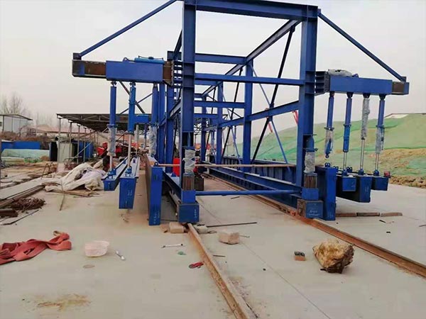
Tunnel formwork channel

3. The core soil method for annular excavation

The following points should be paid attention to in the ring excavation method of retaining the core soil:

(1) The circular excavation footage should be 0.5-1.0m, and the core soil area should not be less than 50% of the entire section area.

(2) Spray anchor support and steel frame support shall be constructed in time after excavation. Adjacent steel frames must be connected by steel bars, and the angle lock anchor rod shall be designed and constructed according to the construction requirements.

(3) When the surrounding rock geological conditions are poor and the self-stabilization time is short, advance support should be carried out according to the design requirements before excavation.

(4) The excavation of the core soil and the lower steps should be completed and the shotcrete should reach 70% of the design strength.

4. Intermediate wall method (CD method)

The CD method is a construction method in which one side of the tunnel is first excavated in a large-span tunnel with weak surrounding rock, and the middle side wall is constructed, and then the other side is excavated. It is mainly used in double-track tunnels with deep buried hard rock in the fourth-level surrounding rock. Lots and old loess tunnels (class IV surrounding rock).

5. Cross-in-neighbor method (CRD method)

The method of intersecting walls is to excavate one or two parts of one side of the tunnel in a large-span tunnel with weak surrounding rock, apply the middle walls and diaphragms of the part, and then excavate one or two parts of the other side of the tunnel to complete Diaphragm construction; then excavate the last part of the first construction side, extend the middle wall, and finally excavate the remaining part. When the short-step method is difficult to ensure the stability of the face, the CRD method with a small section size should be used, which is more advantageous for controlling deformation.

The CD law is the abbreviation of “Center Diaphragm”, and the CRD law is the abbreviation of “Cross Diaphragm”. The two are both related and different. They are used in relatively weak stratum and large section tunnels. The former is a method of excavating by dividing the partition with steel support and shotcrete; the latter is a method of using the partition and invert to divide the section up and down, left and right for excavation, and the geological conditions require that the section is divided. The method adopted under timely closed conditions. Therefore, the only difference between the CRD method and the CD method is that each step of the construction process requires the use of temporary inverts to close the section.

In the CRD method or the CD method, a key issue is the removal of the middle wall. Generally speaking, the middle wall should be removed only after the full section is closed and the displacement of each section is fully stabilized.
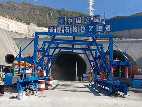
Tunnel formwork channel

6. Double side wall pilot pit method

The double-sided pilot pit method generally divides the section into four sections: the pilot pit on the left and right side walls, the upper core soil and the lower step. The principle is to use two intermediate walls to divide the entire large section of the tunnel into three small sections on the left, middle and right for construction. The hole is temporarily supported to form a full section. The pilot holes on both sides are in the shape of an inverted goose egg, which is conducive to controlling the sinking of the vault.

When the tunnel span is large, the surface subsidence requirements are strict, the surrounding rock conditions are particularly poor, and the single-side pilot method is difficult to control the surrounding rock deformation, the double-side pilot method may be used. Field measurements show that the surface subsidence caused by the double-side pilot pit method is only 1/2 of the short-step method.

Although the double-wall pilot tunnel method has many excavation sections and large disturbances, it takes a long time for the full section of the first support to be closed, but each section is closed immediately after excavation, so there is almost no deformation during construction. develop. The construction of the double-side pilot tunnel method is safe, but the speed is slower and the cost is higher. This method is mainly applicable to formations such as cohesive soil layer, sand layer and sand egg layer.

The construction sequence of the double-side pilot tunnel method is as follows:

(1) Excavate a pilot pit on one side and close it for the first time in time.

(2) Excavate the pilot pit on the other side after a proper distance, and construct the primary support.

(3) Excavate the upper core soil to construct the primary support of the arch, and the arch foot is supported on the primary support of the pilot pit on both sides.

(4) Excavate the lower steps and construct the first support at the bottom to close the full section of the first support.

(5) Remove the first support of the empty part of the pilot pit.

(6) Construct the inner lining.

Pay attention to the following points in the double-side pilot pit method:

(1) The next excavation can be carried out only after the sidewall pilot pit is excavated. When the geological conditions are poor, a temporary steel frame or a temporary invert should be installed at the bottom of each step according to the design requirements.

(2) When each part is excavated, the peripheral contour should be as smooth as possible.

(3) Excavation should be carried out on the other side after the strength of the shotcrete on the first excavation side reaches the design requirements.

(4) The longitudinal spacing of the excavation face of the pilot pits on the left and right sides should not be less than 15 meters.

(5) When the excavation forms a full section, the initial support closure of the full section shall be completed in time.

(6) The partition wall and temporary supports shall be removed section by section when the secondary lining is poured.

How to control the quality of tunnel lining?

Tunnel lining plays an important role in the support of tunnel engineering. It is a permanent support structure built along the periphery of the tunnel body in order to prevent deformation or collapse of the surrounding rock. In actual construction, the quality control of the following links needs to be done. For details, please go to look down.

01. Lining construction

(1) The secondary lining must be carried out when the deformation of the surrounding rock and the initial support is basically stable, and the displacement convergence speed is obviously slowing down, and the various displacements must reach 80% to 90% of the estimated total displacement.

(2) Before the construction of the lining, the waist line must be measured to control the deviation of the invert and foundation pouring, and the lining section base surface and vault elevation should be detected. The thickness error of the tunnel lining meets the design requirements to ensure the clearance height in the tunnel.

Double-track railway lining trolley

(3) The thickness and compactness of the lining must be checked after the construction of the lining, and the electrical signal of the corresponding frequency is generated by the transmitter according to the command of the control unit for detection.

(4) The construction site of the lining must be continuously measured, and continuously collected along the measuring line during the inspection, paying attention to stable movement and uniform speed.

02. Construction of lining structure

(1) Strictly control the mixing ratio of concrete, check the quality of raw materials before mixing, and do not change at will after test verification. Add accelerator according to the construction environment temperature.

(2) In order to ensure the quality of concrete, it must be sprayed with the mixing and continuous spraying; check whether the mechanical equipment is operating normally before construction.

(3) The steel mesh used for lining must be spot welded into blocks at the intersection, and the anchor rods must be laid after completion to ensure that the mesh is close to the initial spray surface. After the construction is completed, the thickness of the concrete protective layer and the connection performance of the steel must be tested.

Water conservancy and hydropower lining trolley

03. Formwork construction

(1) Ensure that the formwork engineering support is firm and stable, and check whether there is excessive deformation and subsidence; the rigidity of the formwork support at the large variable section must be checked, and it must be correctly lofted before installation.

(2) Ensure that the surface of the formwork is cleaned, and the mold release agent is applied to ensure the quality of the concrete molding; during the construction, pay attention to the flatness and tightness of the joints, and there is no hidden danger of misalignment.

(3) The error of each part of the control structure meets the requirements, the elevation of the vault does not exceed 10mm, the error of the center line does not exceed 10mm, and the error of clearance does not exceed 10mm.

04. Crack treatment

(1) Fine cracks can be painted with epoxy resin slurry after cleaning, and then the surface of the concrete can be treated with scraping material and toning material to achieve a beautiful effect.

(2) For penetrating cracks, a V-shaped groove must be cut along the direction of the crack, and drill holes shall be drilled across the cracks in the groove. After removing the debris, the epoxy cement mortar shall be used for anchoring, and the same strength grade cement shall be used to smooth it on it.

(3) Dense cracks must be additionally waterproofed and reinforced. Cement mortar should be injected into the cracks to ensure full grouting; anchor pads should be installed 1 day after grouting, and then filled with epoxy mortar.

Introduction of Safety Technology for Lining Trolley

Lining trolley is a large non-standard mechanical equipment used for secondary lining in tunnel construction. Its main structure is a steel structure combined with plate and beam. It is widely used in the construction of railways, highways and water conservancy and hydropower projects. It is difficult to analyze and calculate the strength and rigidity of its various components and the whole by using traditional mechanical design methods. Therefore, it is necessary to use the safety of the main lining trolley.

1. All formwork trolley operators must pass the safety training examination before they can work.

2. The trolley power supply control distribution box should be placed on the base of the tunnel, and it is strictly forbidden to control the power distribution of the trolley.The box is installed on the trolley, the power cord of the trolley must pass through the leakage switch, and the leakage action of the switch, the current should not be greater than 30mA, the leakage action time should not be greater than 0.1S, and the trolley cable should not there are joints, and the trolley should be reliably grounded.

3. Low-voltage lighting must be used on the lining trolley, and all power lines passing through the formwork trolley, often the lighting line and the template trolley should have insulation facilities, and the electrical line should be suspended, and power is prohibited lines, commonly used lighting lines are placed directly on the ground, or tied to the formwork trolley components,even immersed in water, electric lines that cannot reach a safe distance should be covered when firing the gun.

The tunnel concrete maintenance formwork

4. In the walking, installation and disassembly of the lining trolley, the location of the electric line must be considered will it bring safety hazards to construction operations, especially the walking of trolleys and objects that fall from heights?Damage the electrical circuit and cause a safety accident.

5. The assembly, maintenance and disassembly of the lining trolley should use oxygen, acetylene cutting, electric welding, etc.When working, pay attention to safety and fire prevention.

6. It is forbidden to stack flammable and explosive materials and garbage on the lining trolley; no storage on the template trolley , put other engineering materials and equipment to keep the trolley clean and tidy.

7. The lining trolley platform should be covered with wooden boards, and the wooden boards must be firmly fixed with the trolley.Set up a headboard, and set up a safety net under the formwork trolley at the part where the plank is not fully paved.

8. The installation of the lining trolley; the disassembly and the construction of the second lining should prevent injuries from falling objects from high places people.

9. Before the trolley works, check and ground the trolley. Check the power phase sequence and leakage electric protection device to avoid safety accidents caused by line leakage and motor reversal.

10. When the lining trolley is walking, it should be directed by a special person. The top, front, rear, left, and right sides of the trolley must be protected gang. Operators must follow instructions and strictly guard their jobs.

Tunnel waterproof board laying formwork

11. The moving process should be steady and slow, and it is strictly forbidden to pull, force forward or back.

12. Operators should be assigned to personnel and posts, and should not be replaced at will.

13. After the work is completed, turn off the power, clean up, and stack the second lining according to regulations or requirements.Noted auxiliary equipment and spare parts.

14. Regularly arrange people to maintain the trolley, and add lubricating oil (grease) to each lubrication point.Ensure the flexible use of the trolley.

15. After being in place, a wooden wedge should be added to brake to prevent the lining trolley from shifting.

16. After positioning, the screw jack at the bottom of the trolley should be tightened, and then the two lining trolleys screw the screw jack on the side tightly. When all the screw jacks are tightened, the cylinder jacks should be loosened.The screw jack and the hydraulic jack must be carried out one by one before the concrete pouring and the concrete pouring process.

Pipeline municipal lining trolley

17.Concrete pouring must be carried out evenly and symmetrically, and the height difference between the two sides of the concrete must not exceed 0.6m.Prevent the trolley from being biased.

18. The concrete pouring should be roughly horizontal in the longitudinal direction to prevent the trolley from sliding under force.

19. The pouring speed of the concrete should be strictly controlled to prevent the trolley from floating or being over-stressed and damaging the platform car and personnel casualties.

20. The personnel who watch the mold should seriously check the safety of the concrete pouring, and promptly give a stop if they find a dangerous situation.Stop the concrete pouring signal to prevent the occurrence of construction accidents such as mold running and slurry leakage.

21. Sleeping on the lining trolley is prohibited to prevent smoke and dust poisoning.

The above is all about the safety technology of the lining trolley. I hope it will be helpful to everyone. You must pay attention to safety during the operation of the lining trolley.

Introduction to the Soft Lap Technology of Tunnel Lining Trolley

In order to solve the problem of cracking of tunnel construction joints and the frequently-appearing handover acceptance problem, various construction units have paid a great price to solve this problem. If there is a way to effectively effect the newly poured second lining end during the construction process Protection not only saves a lot of cost, but also improves the quality of the secondary lining to a large extent. Today we introduce in detail a flexible joint device to protect the concrete at the end of the second lining, the soft lap technology of the tunnel lining trolley.

The damage of traditional rigid joint to the end of the second liner

In the secondary lining formwork trolley processing of the tunnel, limited by the factory production conditions and processing accuracy, the contour accuracy of the panels at both ends is not high and cannot be exactly the same, resulting in the slippage of the formwork trolley, due to the forming of the front panel of the formwork trolley There is a difference in shape between the concrete structure surface and the rear-end trolley panel, which cannot be completely coupled. In addition, the concrete pouring process cannot be consistent with the theoretical model. As the number of uses increases, irregular deformations of the formwork trolley panels will be difficult to correct, which will make the coupling problem more serious.

Therefore, during the construction overlap of the front and rear linings, there is a direct topping of the concrete at the overlap due to fear of leakage and tightening of the poured concrete surface, or invisible cracks in the concrete on the early pouring side of the construction joint that cannot be recognized by the naked eye. , During operation, it will fall under the action of the piston pressure difference formed by the high-speed train, jeopardizing driving safety. Moreover, due to the different causes and locations of the arch, the arch has the characteristics of “concealment, suddenness, complexity, and repeatability”. It is a relatively large source of danger for operating tunnels and must be completely eradicated. This problem is currently an important item of lining defects.

Tunnel formwork channel

Introduction to the soft overlap technology of tunnel lining trolley

A compressible rubber gasket is set at the overlapping part of the lining trolley and the upper concrete slab, the compression amount is 50%, the socket type connection, the rubber needs to be customized by the factory, and it is completely elastic and close to contact, so that it will not be crushed. The concrete will not leak, and at the same time effectively prevent misalignment.

In order to prevent the concrete leakage and dislocation at the overlap between the secondary lining trolley and the low side wall of the tunnel, the formwork of the bottom of the lining trolley is anchored with a compressible elastic rubber gasket with a thickness of 5-10mm, which changes the previous hard connection between the trolley and the concrete. For elastic contact, it ensures that the concrete does not leak when vibrating, and eliminates common problems such as misalignment, sandification, and honeycomb pockmark.

As the number of times of use of the tunnel lining trolley increases, the panel will deform to a certain extent. The maximum difference between the front and rear panel contours of the deformed backstage car can reach 2~3cm. With the increase of the number of times of use, the deformation will continue to increase. The soft lap rubber The actual thickness of the strip should be increased during design.

Key points of soft overlap operation of tunnel lining trolley

Lining trolley transformation

The soft overlap pallet of the trolley is processed in advance, and the pallet is welded to the end template of the second lining trolley with bolts, and the trolley panel is 2cm higher than the pallet.

Install the rubber gasket

Install the rubber gasket into the groove of the tray before the trolley is in place. The thickness of the gasket is 4cm (according to the pressure test of the rubber gasket on the hydraulic cylinder of the trolley), and the adjacent circumferential rubber gaskets are connected by socket .

Trolley transformation and positioning

The second liner trolley is in place, the pallet is positioned at the construction joint, and the trolley panel is pushed up to a concrete surface by controlling the hydraulic oil cylinder.

After the rubber gasket contacts the concrete surface, continue to pressurize with the oil cylinder. Observed from the side, when the rubber gasket is compressed to 2cm, the pressure stops. At this time, the trolley panel can be compressed by the compressible rubber gasket to ensure the second liner trolley. The panel is closely attached to the secondary lining concrete surface of the upper one.

Tunnel waterproof board laying formwork

The main solution to the problem of soft overlap of tunnel lining trolley

This process mainly solves the serious problems of tunnel lining during construction. Due to the incomplete coupling of the front and rear panels of the tunnel lining trolley, there are serious problems such as grout leakage, honeycomb pockmarked surface, concrete cracking, and invisible cracks at the circumferential construction joints of each lining concrete. At the same time, due to the construction joints on the basis of the above problems, there are the following two problems:

(1) The ends of the steel-wood combination are easy to cause slurry leakage and under-vibration;

(2) The problem that the construction joint is far away from the feed window and cannot be vibrated. The superimposition of these problems will lead to greater operational safety problems.

Evaluation on the application effect of the soft overlap of tunnel lining trolley and suggestions for improvement

Through the actual construction effect in the tunnel construction, the use of soft lap technology has solved the common quality problems that have existed in the tunnel construction period for a long time, and eliminated the block drop caused by the rigid lap in the operation period.

Of course, the following factors should also be considered in actual use to determine the parameters of the rubber strip:

(1) There are big differences between single-track railway, double-track, and third-track, and construction parameters need to be determined carefully;

(2) The nature of concrete entering the warehouse is different, the lateral pressure is different, the deformation of the trolley and the degree of fatigue resistance are different, and the construction parameters need to be carefully selected;

(3) The rubber strip and the tray should be bonded with welding-free glue;

(4) When opening the rubber strip, the deformation of the trolley should be considered, and the processing size of the rubber strip should be adjusted rationally and flexibly, so as to facilitate the on-site adjustment of measures to local conditions and flexible improvement.