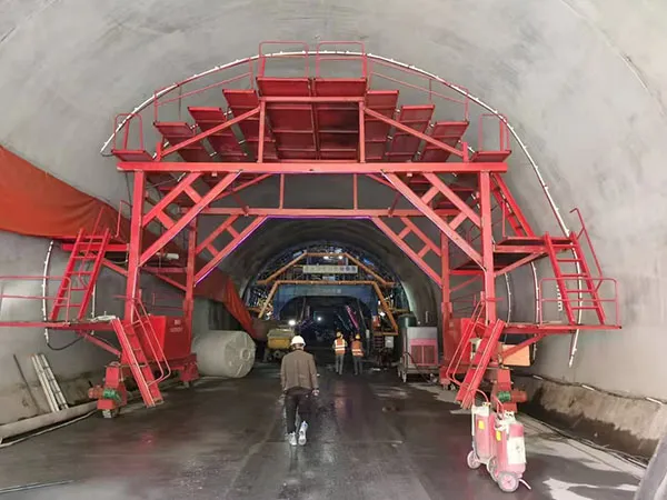
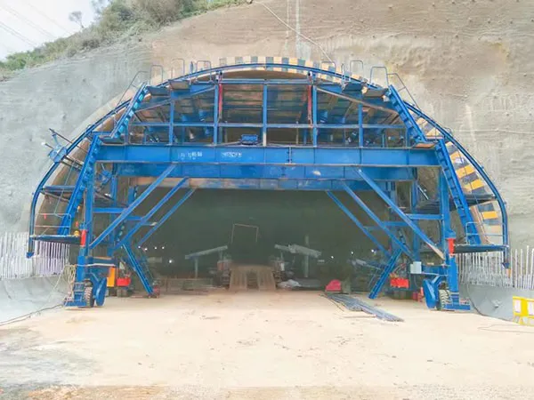
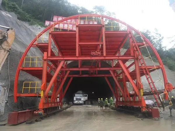
Customizing a tunnel lining trolley (also known as a formwork traveller or gantry) is a complex engineering process, essential for ensuring the trolley perfectly matches the specific requirements of a particular tunneling project. Standard, off-the-shelf trolleys rarely fit unique tunnel geometries, geological conditions, or construction methodologies.

Tunnel Geometry:
Shape: Circular, horseshoe, oval, rectangular, custom profiles.
Size: Specific diameter or width/height dimensions.
Gradient: Inclines or declines in the tunnel.
Curves: Horizontal or vertical curves requiring articulated or adaptable trolleys.
Lining Design:
Segment Length: The length of concrete poured in each cycle dictates the trolley length.
Concrete Thickness: Affects the weight the formwork must support.
Reinforcement: Complexity of rebar cages can influence formwork design and access.
Blockouts & Inserts: Need for openings (e.g., for cross-passages, ventilation, services) requires specific formwork modifications.
Geological Conditions:
Ground pressure might necessitate stronger structural designs or specific anchoring systems.
Concrete Specifications:
Pouring Method: Pumped concrete requires integration points for pipelines (slick lines).
Vibration Needs: Type, number, and placement of vibrators (internal/external) must be specified.
Curing Requirements: Potential need for integrated heating or insulation.
Construction Method & Schedule:
Cycle Time: Requirements for rapid stripping, moving, and setting influence hydraulic speed, automation levels, and overall design efficiency.
Single vs. Double Shell: Different approaches impact trolley design.
Integration: Needs to work seamlessly with other equipment (TBM, waterproofing applicators, rebar jigs).
Logistics & Site Constraints:
Transport Limitations: Size and weight restrictions for getting the trolley to and inside the tunnel. Often requires modular design for easier transport and assembly.
Assembly Space: Limited space at the portal or within the tunnel impacts assembly sequence and design.
Power Availability: Determines whether propulsion and hydraulics are electric or diesel-hydraulic.
Safety & Regulations:
Specific requirements for walkways, railings, emergency stops, lighting, ventilation, fire suppression, and access/egress.
Based on the needs, specific components and systems of the trolley are customized:
Dimensions & Profile: The most fundamental customization – matching the exact tunnel cross-section and segment length.
Structural Frame (Gantry): Designed and calculated (often using Finite Element Analysis - FEA) to safely support the weight of the wet concrete, the formwork itself, personnel, equipment, and potentially some ground pressure. Material selection (steel grades) is critical.
Formwork Panels (Shuttering):
Material: Typically steel, thickness varies based on pressure.
Surface Finish: Smoothness requirements for the concrete surface.
Joints: Design for tight seals to prevent grout leakage.
Modularity: Designing panels for easier handling, stripping, and cleaning.
Inspection Hatches & Access Ports: Custom placement for monitoring concrete pour and vibration.
Blockout Integration: Precise design to incorporate required openings.
Hydraulic System: Customised for:
Lifting/Lowering: Capacity and speed for raising/lowering the main gantry.
Formwork Stripping & Setting: Mechanisms (often hydraulic cylinders) to collapse the formwork slightly for moving and expand it tightly against the previous segment or rock face.
Anchoring/Bracing: Systems to hold the trolley securely in place during concrete pouring.
Propulsion Assist: Sometimes used in conjunction with electric drives.
Propulsion System:
Type: Electric motors (most common) or hydraulic drives.
Drive Mechanism: Wheels on rails, wheels on concrete invert, or sometimes crawler tracks.
Speed & Control: Variable speed control for precise positioning.
Steering: Mechanisms for navigating curves (e.g., articulated sections, bogies).
Vibration System:
Type: External form vibrators (most common) or internal poker vibrators.
Placement & Number: Strategically located for optimal concrete consolidation.
Control: Frequency and amplitude control, zoned operation.
Working Platforms & Access:
Custom-designed platforms, stairs, ladders, and safety railings for worker access during rebar placement, concrete pouring, inspection, and finishing.
Integration with emergency escape routes.
Control System:
Manual, semi-automated, or fully automated PLC-based controls.
Operator cabin design and location.
Remote control options.
Sensors for monitoring pressure, position, vibration, etc.
Utilities Integration:
Mounting points and routing for concrete delivery pipes.
Cable reels and routing for electrical power.
Connections for water (cleaning) and compressed air.
Integrated lighting and ventilation ducts if required.
Modularity & Transport: Designing the trolley in sections (modules) that meet transport size/weight limits and facilitate easier assembly/disassembly underground.

Requirement Gathering: Detailed discussions between the client (contractor/project owner) and the manufacturer's engineering team. Provision of all relevant project data (tunnel drawings, geological reports, concrete specs, schedule, site constraints).
Conceptual Design: The manufacturer develops initial concepts and layout drawings based on the requirements. Feasibility checks are performed.
Detailed Engineering: Creation of detailed manufacturing drawings, structural calculations (FEA), hydraulic schematics, electrical diagrams, and control system logic.
This involves significant engineering work.
Client Review & Approval: The client reviews the detailed design package to ensure it meets all specifications before manufacturing begins. Iterations may be necessary.
Manufacturing & Fabrication: Building the trolley components according to the approved drawings. This involves steel cutting, welding, machining, painting, and assembly of sub-systems. Quality control is critical throughout.
Factory Acceptance Test (FAT): Partial or full assembly of the trolley at the manufacturer's facility. Testing of all systems (structural integrity checks, hydraulic movements, electrical controls, propulsion) to ensure functionality. The client typically witnesses the FAT.
Disassembly & Shipment: Breaking down the trolley into transportable modules, packing, and shipping to the project site.
On-Site Assembly & Commissioning: Re-assembling the trolley at the tunnel portal or inside the tunnel under the supervision of the manufacturer's technicians. Final testing, adjustments, and integration with site systems.

Training & Handover: Training the client's operators and maintenance crew on the specific operation and upkeep of the customized trolley. Provision of detailed manuals and documentation.
Ongoing Support: Manufacturer provides spare parts, technical support, and potentially maintenance services throughout the project lifecycle.
Customizing a tunnel lining trolley is an essential, engineering-intensive process that tailors the equipment to the unique demands of a specific project. It involves close collaboration between the project team and the manufacturer, detailed analysis of project requirements, and careful design across multiple disciplines (structural, mechanical, hydraulic, electrical, control systems). The result is a bespoke machine optimized for safety, efficiency, and quality in tunnel construction.
Gaofei
Address: 200m east of tulip garden, group 12 of zhangling community, hongshan street office, hongshan town, xigong district, Luoyang
Tel: +8616638856888
Contact: Gaofei Huang
Mobile: +86-18637923976
Phone: 0379-80881719/ 0379-60162687
QQ: 286827457
E-mail: gaofei@gf-bridge-tunnel.com