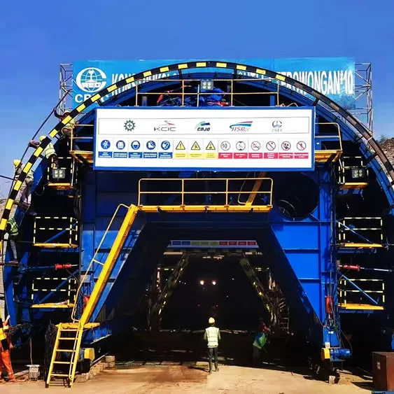
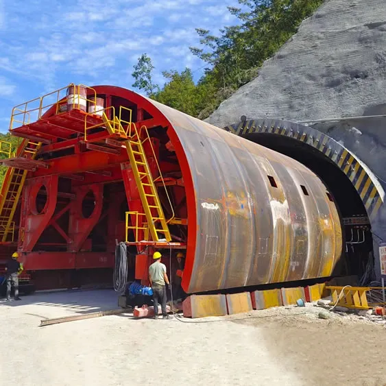
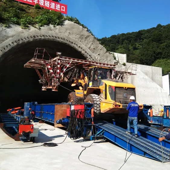
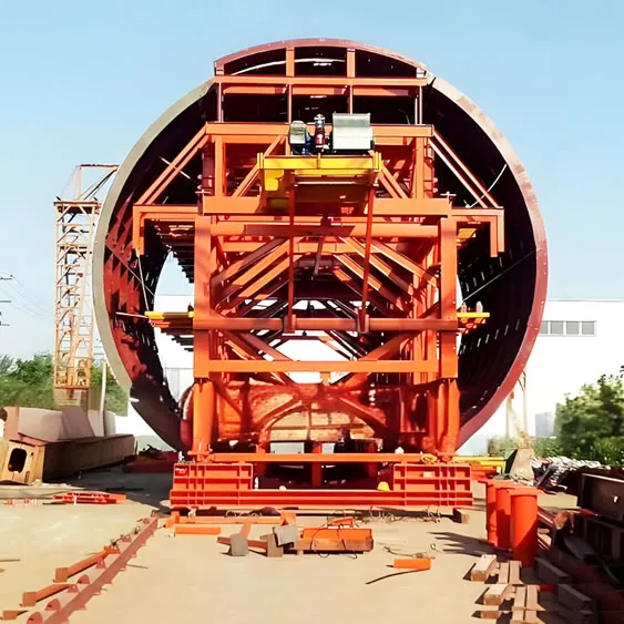
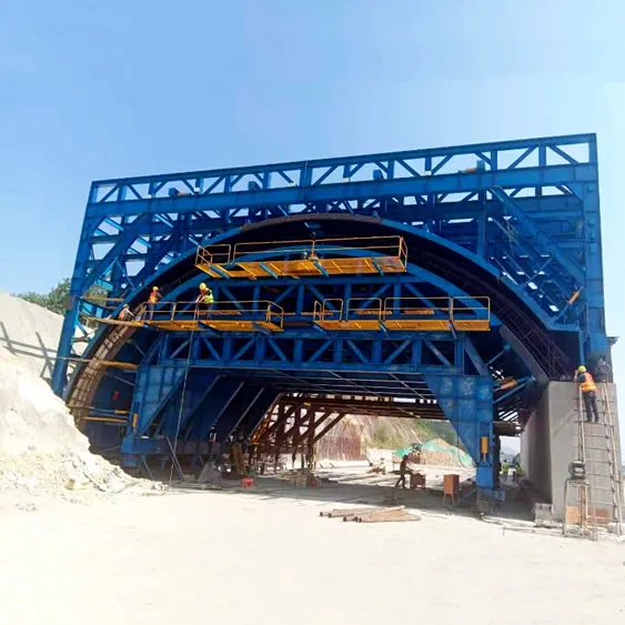
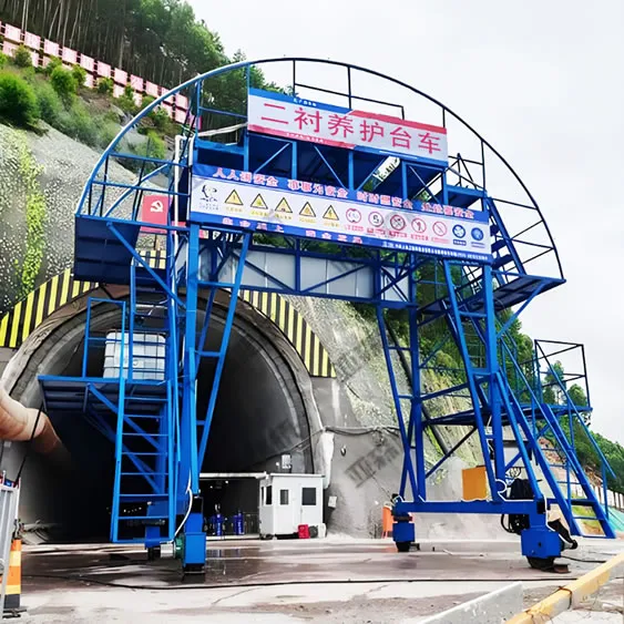
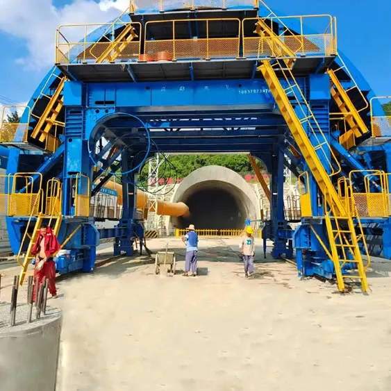
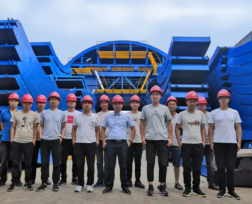
Crawler Hydraulic inverting bridge formwork
Inverted arch construction is a key process of construction efficiency and quality control. In order to reduce the interference of the inverting arch construction on the vehicle transportation in the tunnel, the new hydraulic crawler hydraulic inverting bridge formwork is adopted. The trestle is compact and realized. Quickly moving in place, reducing labor intensity, ensuring construction safety and improving construction efficiency.
1. technical parameters
- Open weight limit: <60T (excluding self weight)
- Opening limit <3.4m
- Effective span of 17m
- Safe step: V-class surrounding rock, from the face of the face, 35m of the inverting arch, 70m of the second lining
- Working mode: hydraulic
- Walking method: crawler self-propelled
2. the main parameters of the product
Appearance size (m): 30 (length) × 3.6 (width)
Product weight: about 52t
Maximum walking speed: 25 m/min
Approach bridge slope: ≤12°
Driving force: 120 KN
Total power: 18.5 Kw
Walking state grounding specific pressure: ≤ 0.1 MPa
Open state grounding specific pressure: ≤ 1 Mpa
Crawler Hydraulic inverting bridge formwork Structural calculation
(force analysis)
The trestle structure consists of two I25b I-beams arranged side by side as longitudinal members. The upper and lower flange plates of each of the two I-beams are welded long, and the horizontal top is connected with Φ22 threaded steel bars to ensure that the longitudinal beams can be combined under the load of the wheels. Forced and able to increase the lateral stiffness of the trestle deck.
1. Mechanics simplification
Both ends of the beam have the possibility of rotation and expansion, so the calculation diagram can be simply supported. Since the bending moment on the section changes with the position of the load, the maximum normal stress on the dangerous section, ie the maximum bending moment section, should not exceed the bending allowable stress of the material [σ] when calculating the structural strength. Therefore, it is necessary to determine the most unfavorable position of the load. When comparing the bending moments at different positions of the load, the P/3 load should be taken at the mid-span position when the maximum normal stress is checked. When calculating the maximum shear stress, take the load close to the bearing position.
2. Checking process
(1) Trestle structure check
1) Calculate the reaction forces of the bearings A and B and the maximum bending moment and shear force by static balance
N p 531053. 21. 115. 1101020⨯=⨯⨯⨯⨯=
N p L p R Ac 51053. 0245431⨯==÷⨯= N p L L p p R Ad 51005. 1417. 02. 36131⨯==-⨯+=
KN R Q m KN L R M Ad Ac 2max 25max 1005. 1107. 12. 31053. 02⨯==∙⨯=⨯⨯=⨯
=
p — vehicle load (N )
RAc – A fulcrum reaction force (N ) in Figure c
RAd – A fulcrum reaction force (N ) in Figure d
Mmax – maximum bending moment value (KN.m)
Qmax – maximum shear value (KN)
2) Mechanical calculation according to the primary selection structure:
According to the calculation of the total of 6 I-beams on each side, check the “Bridge and Bridge Construction Calculation Manual” – the section of the hot-rolled ordinary I-shaped steel section, and obtain the I20b type I-beam.
- 250cm W x =; 31. 33cm W y =
In-plane intensity calculation;
[]MPa MPa Wx M w 2102. 1132. 2506107. 15max max =<=⨯⨯==σσ Σmax-----maximum bending stress of I-beam (MPa) [σ]-----Steel allowable bending stress (MPa) Wx-----x axis section resistance moment (cm3) Wy----- y-axis section resistance moment (cm3) It can be seen from the above calculation that one side is selected according to six I-beams, the in-plane strength can meet the working requirements, and the margin coefficient of the interaction between the I-beam and the transversely-connected reinforced bar is not considered, and the in-plane is safe. Out-of-plane intensity calculation Considering that the vehicle is traveling on the trestle, the direction is not necessarily parallel to the longitudinal direction of the bridge. There is a transverse bending moment. Considering 15% of the maximum bending moment of the plane, the calculation is as follows: []MPa MPa W M w y 2104. 1281. 33615. 0107. 15max max =<=⨯⨯⨯==σσ It can also be seen from the above calculation that according to the selection of six I-beams on one side, the out-of-plane strength can meet the design requirements. Shear stress calculation Using the shear stress strength condition formula to check the maximum shear stress, first calculate the static moment of the area of the neutral axis on the side of the neutral axis of the I20b I-beam. max x S The maximum shear force shared by each I-beam is KN Q 5. 1761005. 12 =⨯= Check the I25b type I-beam 42505cm x =I, 31. 146cm S x = Cm S x x 17:=I , mm d 9= Therefore, the maximum shear stress of the longitudinal beam of the trestle is obtained, and the shear stress strength is checked accordingly. []MPa MPa d S Q x x 1203. 11925051. 1465. 17max max =<=⨯⨯=∙I∙=ττ Τmax ---maximum shear stress [τ] ---Steel allowable shear stress (MPa) Q----shear force (KN) Sxmax---Maximum half-section area moment (cm3) Ix----axis moment of inertia (cm4) d----web thickness (mm) The shear stress meets the requirements and the structure is safe. 4)), stiffness calculation: General simple supported beam structure allows deflection For structures with high deflection requirements, Mm L f 164004. 6400][==⎥⎦⎤⎢⎣⎡=, a structure that requires less deflection, Mm L f 262504. 6250][==⎥⎦⎤⎢⎣⎡=, Mm EI Pl f 6. 1462505101. 2484. 61053. 2333. 0485353max =⨯⨯⨯⨯⨯⨯⨯== []mm f mm f 166. 14max =<=; []mm f mm f 266. 14max =<= Fmax — maximum deflection value (mm) [f]---allow deflection value (mm) p---back axle load (N) L---calculation span (m) E---Modulus of elasticity (MPa) The maximum deflection of the trestle is less than the required structural deflection allowable value, and the trestle structure is available. Second, 1.3 main components of the structure The product is mainly composed of the guide bridge part, the driven walking system, the fixed support of the feeding end, the main bridge, the crawler walking system, the fixed support of the excavation end, and the hydraulic system. (1) Approach bridge: It consists of the excavation end approach bridge and the lining end guide bridge. The main body of the approach bridge is welded by I25b steel and φ32 thread steel. The approach bridge is lifted and lowered by hydraulic cylinder. Among them, the excavation end approaching bridge is designed to ensure effective contact on the uneven ground, and the left and right parts can be separately raised and lowered. (2) Fixed support at the feeding end: As the bearing structure when the working end of the tresting end is working, in order to reduce the grounding specific pressure and protect the concrete filling surface, the contact surface of the fixed support and the concrete adopts a monolithic steel plate structure. (3) Driven walking: The driven walk is designed to be a telescopic structure through the cylinder, and the solid tire only contacts the feed surface when it is in the walking state. (4) Main bridge: The main structure of the main bridge is the bearing capacity when the trestle is working. It is necessary to ensure the safe and reliable passage of the construction vehicle. The main body is made of longitudinal beam H250×250 steel, beam I20b steel and bridge surface φ32 thread steel, and 300mm high tire limit baffle is arranged on both sides. (5) Fixed support at excavation end: As the bearing structure when the excavation end bridge is in working condition, since the top surface of the working surface is curved, the support is designed as a “ship type” structure, to reduce the ground specific pressure and prevent subsidence. The contact surface between the fixed support and the ground adopts a monolithic steel plate structure. (6) Hydraulic system: mainly includes hydraulic pump station, approach bridge lifting cylinder, main/slave walking lifting cylinder and crawler driving motor; pump station and cylinder are all mature products, and the system reliability is good. (7) Track walking system: It adopts two crawler belts for parallel use, which is a mature product in China. To enhance system reliability, the drive motor adopts imported brand. The “four wheels and one belt” is a standard model for easy maintenance. [/av_tab] [av_tab title='3. Technical requirements' icon_select='no' icon='ue800' font='entypo-fontello' av_uid='av-aae0fq']
3. Technical requirements
(1) The bridge must have a structural checklist and meet the requirements for use.
(2) Before the bridge moves, the tunnel bottom should be cleaned up without large gravel and debris.
4. Construction procedures
The trestle bridges the following four states to meet the needs of the construction for its various positions and postures.
(1) Open state: The main/slave traveling cylinder shrinks, and the fixed support is used as the force-receiving structure before and after the trestle; the suction end/excavation end guide cylinders are all contracted, and the approach bridge is grounded.
(2) Bottom mounting state: The main/slave traveling cylinder shrinks, and the fixed bridge is used as the force-receiving structure before and after the trestle; The excavator is bottomed and installed at the front end of the raised approach bridge; the earth-moving vehicle is docked at the excavation end of the trestle to receive the decoration.
(3) Preparing the walking state: the main/slave walking cylinder is extended to make the walking contact with the ground beyond the fixed support; the suction end/excavation end guiding cylinder is extended, and the approaching bridge is lifted off the ground;
(4) Walking in position: After the trestle advances 2m, it starts to be in position. First, the main/slave walking cylinder contracts, so that the front and rear fixed supports act as the force-bearing structure; the approaching bridge cylinder contracts, the approach bridge stands, the in-position action is completed, and the lower cycle begins. Construction work.
5. Construction requirements
5.1 Construction preparation
Plan the processing of personnel, materials, and machinery in advance. The technical and safety of the operators will be carried out by professional technicians.
5.2 Trestle inspection
Before the trestle is moved, erected and installed, there shall be no weld seams and cracks in the welded joints of the trestle. The support system shall be inspected to check whether the main girder and auxiliary members of the trestle are cracked or deformed. Move and erect, move and erect the trestle after the process is completed and checked.
5.3 Trestle movement
Use the excavator or loader to be in place, and walk by itself after the position; the concrete strength of the inverted arch meets the design requirements and the necessary protective measures are taken before moving, the movement must be slow, and the damage to the quality of the finished product is avoided; When moving, a full-time staff must be assigned to command, and it is strictly forbidden to stand in the trestle work area.
5.4 Trestle erection and installation
Crawler Hydraulic inverting bridge formwork When erecting, the bottom slag of the platform before the trestle shall be removed before the trestle is advanced. The foundation must have a certain bearing capacity. The rear end is laid on the top surface of the filling; the front end ramp of the trestle bridge should be firmly connected with the trestle platform to ensure the safety of the erection. After the erection of the trestle is installed, the safety net must be placed on the guardrails on both sides of the trestle to prevent the gravel from falling and injuring the construction operator below the arch; the obvious warning signs should be set before and after the trestle and the surface of the trestle should be anti-slip
6. Material requirements
(1) Various steel materials for Crawler Hydraulic inverting bridge formwork comply with national standards and have factory certification.
(2) Cracks, folds, knots, and inclusions are not allowed on the surface of the material; delamination and shrinkage marks are not allowed at the ends.
7. Equipment and equipment configuration
1, the bridge foundation
Crawler Hydraulic inverting bridge formwork The supporting foundation must be solid and stable. The length of the bridge between the trestle and the unexcavated surface must not be less than 50cm.
Trestle operation
2, check
During the use of the trestle, it is found that the deflection is too large or exceeds the requirements and should be repaired in time.
Before the trestle is moved, erected and installed, there shall be no weld seams or cracks in the welded joints of the trestle.
The main beam of the trestle beam and the upper and lower steel plates have no cracks, oil stains, granular or flake rust.
8. Safety and environmental requirements
(1) Because the earth-moving vehicle is parked at the position of the slope of the susceptor bridge when the bottom is installed, in order to provide the parking position and prevent the rolling, the bridge is provided with the lifting and lowering of the approaching bridge. Blocking device
(2) In order to prevent the splash of stones during the blasting process, it is necessary to protect the important parts of the trestle. Taking into account the transportation and other issues, the pavement design is two left and right, in order to effectively protect the lower part of the trestle, and also for the safety of personnel walking, it is recommended to lay a mesh between the two pavements after the installation of the trestle hole is completed.
(3) Hydraulic system protection measures: In addition to the personnel operation surface of the hydraulic pump station operation table, the other three sides and the top of the three sides and the top to make the closed guard plate, hydraulic pipeline layout as far as possible in the steel tank or the bottom of the bridge.